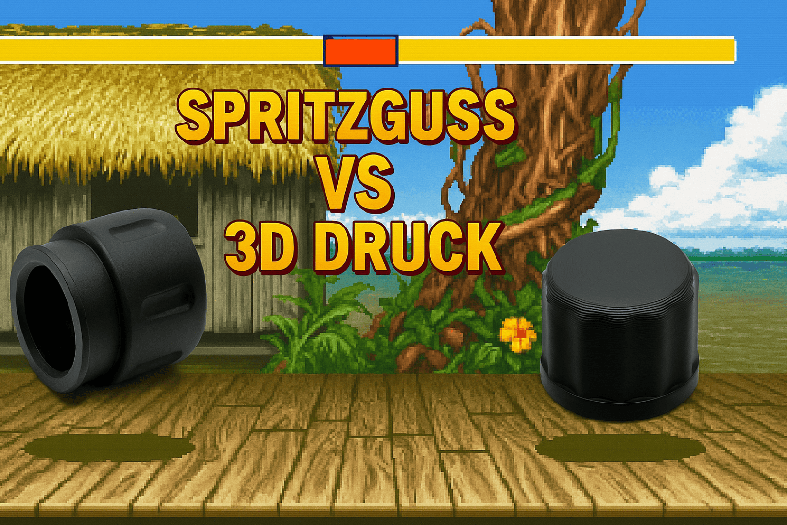
Which is better, injection molding or 3D printing?
We pitted the two technologies against each other using specific practical examples. Surface quality, material variety, precision and costs: we reveal which process comes out on top.
Choosing the right production technology is crucial for the cost-effectiveness and quality of your plastic parts. Especially for development and design, the question often arises: 3D printing or injection molding? We would like to use two real components to illustrate the differences and help you decide.
Torson Injex AG not only produces high-quality injection molded parts, but recently also 3D printed parts from the FDM printer. This showcase is intended to provide a clear overview of the advantages and disadvantages of the two technologies and in which case which manufacturing process is more suitable.
In order to make a meaningful comparison, we have taken two similar components, both of which are in production at our company. One is manufactured using injection molding and the other using the FDM process. Both components are similar in size and have an internal thread.
 |
 |
| Injection molded threaded sleeve | End cap FDM part |
In injection molding, plastic is heated until it melts and then injected into an injection mold to create the desired shape. Once the plastic has cooled and solidified, the component is removed from the mold (also known as the tool).
In the 3D printing process FDM (Fused Deposition Modeling), a plastic filament is melted and pressed through a fine nozzle. The nozzle then builds up the component layer by layer from thin “plastic sausages”.
In the following, the two technologies are compared with each other in various aspects.
Note: The statements made here are to the best of our knowledge and belief. Torson Injex AG has no interest in persuading readers to use one or the other method. Our aim is to provide an objective comparison.
The comparison:
Surface and appearance
 |
 |
| FDM layer structure | FDM weld line |
The surface quality of FDM components has improved significantly in recent years. Nevertheless, an experienced eye can immediately distinguish whether a component comes from a 3D printer or an injection mold.
In the FDM process, the components are built up layer by layer. Usually with a layer thickness of between 0.1 and 0.4 mm. This layering is also clearly visible in the end result.
Another optical aspect of the FDM process is the so-called weld line. This is the point at which the print head starts and finishes the outermost layers. The point is often selected so that it is more or less in the same place in each layer. This creates the weld line. There are strategies to minimize this. However, it cannot be completely eliminated.

The injection molding process offers much finer adjustment options here. In this example, the surface of the component was eroded. This makes it possible to achieve specific and precise surface roughness values. Everything is possible, from highly polished surfaces to rough textures.
The only imperfections in the surface of the injection molded part are the injection point and the mold parting line, where the two halves of the injection mold meet. Many components also have ejector marks, which are not present on this component.
Materials and properties
The number of processable materials for the FDM process has once again increased significantly in recent years. The most common printing materials include PLA, ABS and PET-G. However, PC, PA, PPS, PEEK, PP and other materials are now also available. Mostly also in fiber-reinforced versions.
Injection molding, however, offers another order of magnitude of choice. There are well over 10,000 different materials with all possible combinations of additives, reinforcements, certifications and special properties. Injection molding is particularly superior in the field of elastomers.
Injection molding is also ahead when comparing mechanical properties. The layered structure of FDM components always leads to a reduction in resilience and anisotropic behavior. Here too, there are strategies to reduce this effect. Ultimately, an injection-molded component will always be superior to an FDM-printed component made from the same material.
Tolerances
There are various standards for defining and estimating tolerances for injection molded components. One of the most widely used is DIN ISO 20457, which specifies tolerances according to tolerance classes and subdivides them depending on the nominal dimension and distinguishes between mold-related (W) and non-mold-related dimensions (NW). A small excerpt from such a tolerance table is shown here.

To the best of our knowledge, no separate tolerance standards have yet been established for FDM components. We therefore use the same tolerance classes for this comparison as for injection molded parts. The tolerance classes TG4 to TG7 are often used for classic injection molded parts. Which class is used ultimately depends on the material used, the shrinkage behavior and the wall thickness distribution. The tolerance class can be improved by one point by means of precision manufacturing.
For the injection-molded component threaded sleeve, which is injection-molded in a reinforced plastic with uniform wall thickness distribution, most masses fall into tolerance class TG4 and for some masses even class TG3 is achieved. For the FDM component end cap, tolerance classes in the range TG6 to TG4 are achieved, whereby an iterative improvement of specific dimensions is necessary for TG4.
Functionality
Both components have an internal thread. The functionality of the thread and the screw connection are therefore compared for this comparison.
 |
 |
| FDM part end cap on connector | FDM layered structure in the thread |
The components are even screwed together with the same counterpart in the application. The end cap is a transport protection for the connector and the threaded sleeve is a component of the associated coaxial/triaxial plug, which is connected to it.
The end cap from the 3D printer can be easily screwed to the thread. Although you can clearly see the layering of the printing process in the thread, the screw connection is clean with only very slight friction effects.

The injection-molded threaded sleeve can of course be screwed to the counterpart without any play and extremely smoothly.
Design
One of the biggest and most important advantages of 3D printing is the almost limitless freedom of design. If you want to work without support structures, it is important not to design too much overhang (angle from the outermost layer to the next layer). Otherwise, there are almost no obstacles. Undercuts, threads and other complex structures, which are feasible but very costly in injection molding, pose no problems here.
In addition, very uneven wall thicknesses, cavities or other geometric properties that are impossible with injection molding can be designed and implemented. In the practical example shown, both components, the threaded sleeve and the end cap, can be produced using both processes.
Lead-times
3D printing is also clearly superior to injection molding in terms of time. Torson Injex can probably justifiably claim to have one of the fastest processes for the production of injection molded parts in the world. Thanks to an additive tooling process (the tools come from the 3D printer - but not an FDM machine), real injection molded parts can be produced in just a few days. In classic injection molding, waiting times of several weeks to months are often to be expected.
3D printing is different. As soon as the design is finalized, the first prototype can be held in the hand within a few minutes to hours. Further iterations and design adjustments, which quickly take days and weeks in injection molding, can be implemented in no time with 3D printing.
Cost
When it comes to costs, things are a little more complex. There are two cost items in injection molding. The mold and the part price. The more components you want to produce, the more cavities you need in the mold in order to be able to inject several components at once. The mold costs therefore depend not only on the component geometry, but also on the targeted quantity.
In the FDM process, no mold is required and only the unit costs are decisive. However, these scale significantly worse than in the injection molding process. Below is an overview of the cost structures:

Choice of technology
Whether injection molding or FDM printing is more suitable for an application depends on various factors. Here is a simplified decision tree (in German), which should be helpful for the evaluation.

The decision for the components shown here was as follows:
- Threaded sleeve: This component is suitable for injection molding but an FDM look is not acceptable. Therefore, the component must be injection molded.
- End cap: This component would be suitable for injection molding but an FDM look is acceptable for the application and all functionalities can be fulfilled. With a required quantity of 10,000, the unit price would be better with injection molding. However, if the initial costs for the tool are taken into account, the decision is made in favor of the FDM process.
Conclusion
In recent years, FDM printing has established itself as a tried and tested manufacturing process for plastic parts. In many respects, a 3D-printed component is clearly inferior to an injection-molded part. In terms of appearance, material selection, properties and functionality, injection molding is almost always ahead. The fantastic design freedom and the fact that there are no initial costs speak in favor of 3D printing.
In a nutshell: FDM is ideal for small series and prototypes with fewer demands on surface finish and strength. For series products with high precision, mechanical resilience and surface quality, injection molding remains the preferred choice.


